| .. | ||
| tests | ||
| .gitignore | ||
| __init__.py | ||
| camera.py | ||
| coordinates.cc | ||
| coordinates.hpp | ||
| coordinates.py | ||
| model.py | ||
| orientation.cc | ||
| orientation.hpp | ||
| orientation.py | ||
| README.md | ||
| SConscript | ||
| setup.py | ||
| transformations.pxd | ||
| transformations.pyx | ||
Reference Frames
Many reference frames are used throughout. This folder contains all helper functions needed to transform between them. Generally this is done by generating a rotation matrix and multiplying.
| Name | [x, y, z] | Units | Notes |
|---|---|---|---|
| Geodetic | [Latitude, Longitude, Altitude] | geodetic coordinates | Sometimes used as [lon, lat, alt], avoid this frame. |
| ECEF | [x, y, z] | meters | We use ITRF14 (IGS14), NOT NAD83. This is the global Mesh3D frame. |
| NED | [North, East, Down] | meters | Relative to earth's surface, useful for vizualizing. |
| Device | [Forward, Right, Down] | meters | This is the Mesh3D local frame. Relative to camera, not imu. 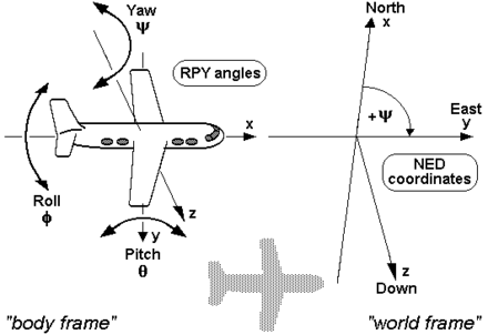 |
| Road | [Forward, Left, Up] | meters | On the road plane aligned to the vehicle.  |
| View | [Right, Down, Forward] | meters | Like device frame, but according to camera conventions. |
| Camera | [u, v, focal] | pixels | Like view frame, but 2d on the camera image. |
| Normalized Camera | [u / focal, v / focal, 1] | / | |
| Model | [u, v, focal] | pixels | The sampled rectangle of the full camera frame the model uses. |
| Normalized Model | [u / focal, v / focal, 1] | / |
Orientation Conventations
Quaternions, rotation matrices and euler angles are three equivalent representations of orientation and all three are used throughout the code base.
For euler angles the preferred convention is [roll, pitch, yaw] which corresponds to rotations around the [x, y, z] axes. All euler angles should always be in radians or radians/s unless for plotting or display purposes. For quaternions the hamilton notations is preferred which is [qw, qx, qy, qz]. All quaternions should always be normalized with a strictly positive qw. These quaternions are a unique representation of orientation whereas euler angles or rotation matrices are not.
To rotate from one frame into another with euler angles the convention is to rotate around roll, then pitch and then yaw, while rotating around the rotated axes, not the original axes.
Calibration
Device frame is aligned with the road-facing camera used by openpilot. However, when controlling the vehicle it makes more sense to think in a reference frame aligned with the vehicle. These two reference frames are not necessarily aligned. Calibration is defined as the roll, pitch and yaw angles that describe the orientation of the vehicle in device frame. The vehicle orientation is the orientation of the vehicles's body, the orientation of the vehicle can change relative to the road because of suspension movements.
The roll of the vehicle is defined to be 0 when the vehicle is on a flat road and not turning. Pitch and yaw are defined as the angles that describe the direction in which the vehicle travels when it is driving on a flat road and not turning.
It is important for openpilot's driving model to take in images that look as if the calibration angles were all zero. To achieve this the images input into the model are transformed with the estimated calibration angles. At the moment, roll calibration is always estimated to be zero.
Example
To transform global Mesh3D positions and orientations (positions_ecef, quats_ecef) into the local frame described by the first position and orientation from Mesh3D one would do:
ecef_from_local = rot_from_quat(quats_ecef[0])
local_from_ecef = ecef_from_local.T
positions_local = np.einsum('ij,kj->ki', local_from_ecef, postions_ecef - positions_ecef[0])
rotations_global = rot_from_quat(quats_ecef)
rotations_local = np.einsum('ij,kjl->kil', local_from_ecef, rotations_global)
eulers_local = euler_from_rot(rotations_local)