3.4 KiB
Detector Signals of Radioactivity on an Oscilloscope
The screenshots below show typical output signals from both detector variants with arrows highlighting the signal and noise properties. The blue lines represent signals from individual particles, the grey lines are superpositions of earlier particle signals which triggered the oscilloscope as well.
For a better comparison between the two detector variants, the same beta & gamma radiation source (potassium salt, KCl) was used in both measurements below - it does not emit alpha particles.
The negative pulse with its steep downward edge is the main signal and is larger than the electronic noise. The trigger level must be set well below the noise range, which depends on the intensity of surrounding electromagnetic interference (EMI) radiation and stray light reaching into the shielding case of the detector. The short negative main signal pulse is followed by a wider positive overshoot which is proportional in size to the amplitude of the main signal. The overshoot is an effect of the amplifier circuit and also depends on the impedance matching from the detector output to the input of the measurement device. The employed oscilloscope features a default input impedance of 1 megaohm. Microphone and line-in inputs of sound cards (as described above) have considerably lower input impedances and pulse measurements will therefore show a larger signal overshoot. The alpha-spectrometer circuit was intentionally designed to produce this kind of a bipolar signal with a lot of overshoot in order to mimic actual audio waves.
If the detector signals do not look similar to the ones below, please follow the Troubleshooting guide!
Electron-Detector
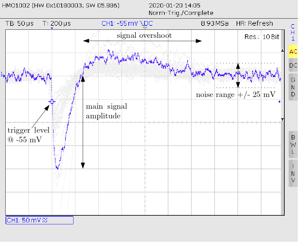
Time Scale: 50 Microseconds per division, Voltage Scale: 50 Millivolt per division
Real pulses from particles can be typically well distinguished from electronic noise at trigger level of about -50 mV (and lower) if the detector is well shielded against surrounding light and not exposed to electromagnetic interferences, e.g. from a cell phone, power supply or electromotor close by. The negative pulses are about 50 to 75 us wide with this circuit.
Alpha-Spectrometer
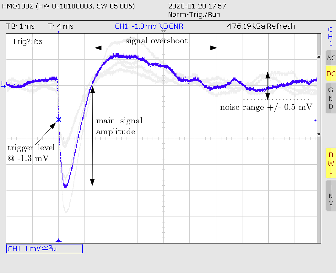
Time Scale: 1 Millisecond per division, Voltage Scale: 1 Millivolt per division
Typical signal amplitudes of particles from the same beta/gamma radiation source are much lower compared to the electron-detector variant. The electronic noise is much smaller as well and the width of pulses is between 1 and 2 ms. This circuit is optimised for large pulses from alpha particles which is heavy-ionizing radiation and therefore produces a lot more free charges in the sensor.
The amplitude threshold which allows distinguishing between electrons (=smaller signal amplitude) and alpha particles (=larger signal amplitude) is at -8 mV in case of a typical oscilloscope with an input impedance of 1 megaohm. This threshold is lower in case of a sound card due to their lower input impedances. Please refer to the scientific article and the energy calibration function for detailed information.